")


PTP Clock Check
In PTP clock , generally supports many PTP type (P2P , E2E, etc.)
So, in PTP topology design, we need to check all PTP switch and PTP clock is same PTP type
Below is our test example,
I use OMICRON “ OTMC 100p “ PTP clock . and ORing 9000 series switch.
1. PTP Clock Type Check
As below screenshot, the PTP CLOCK Setting Type = P2P
Therefore, ORing switch also need to work in P2P mode.

2. Operation mode c onfiguration
PTP have two operation modes ,One Step and Two Step.
ORing 9000 series switch only support Two step mode .
Please change PTP Clock operation mode = Two Step .

3. Test Topology .
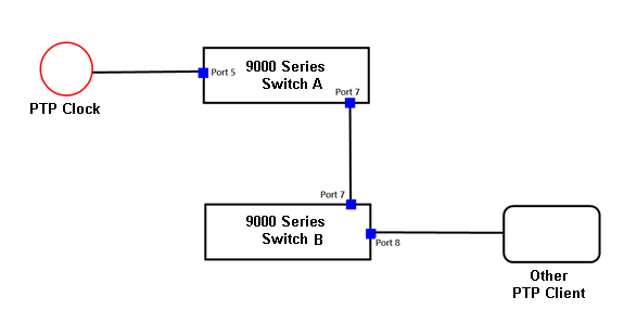
Check item:
1、 Two Switch PTP Master / Salve Status
2、 Two Switch PTP P offset from master field need get value .
3、 Two Switch and PTP Client can get PTP CLOCK TIME INFO .
Switch A Configuration
First, create a PTP Entry , Device type = Ord-Bound , other value keep default.
And select PTP work port. (in this example , we use port 5 and port 7 )
PORT 5-->PTP Clock
PORT 7-->Switch B

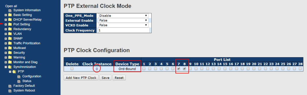
Next click ClockInstance number , into PTP Port config page .
Click Port configuration
Change DIM field same PTP Type ,
Now PTP TYPE = P2P , so , Switch DIM need change to P2P

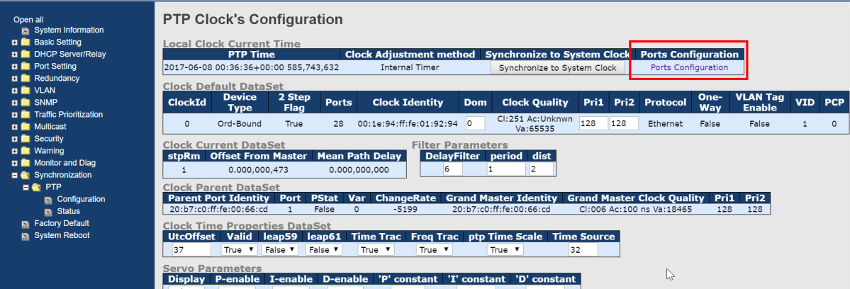
Wait some sec , in switch PTP Time field will get time.
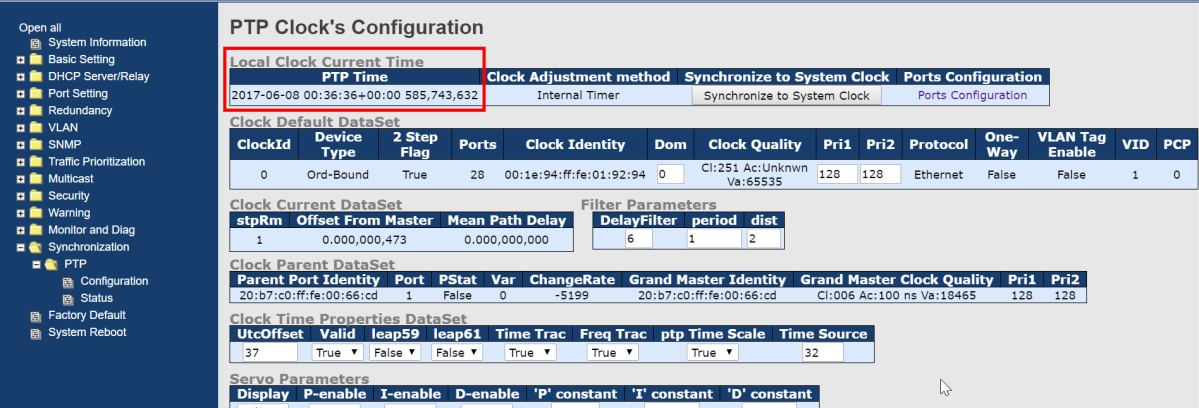
And , please check Offset From Master field the field should be have value ,
Indicates that SWITCH has correction time!

Switch B Configuration
All setting same Switch A , First , create a PTP Entry , Device type = ord bound , other value keep
default . And select PTP work port . (in this example , we use port 7 and port 8 )
PORT 7 -->Switch A
PORT 8 -->Other PTP Client
Next click CLOCK Instance number , into PTP Port config page
Click Port configuration

Change DIM field same PTP Type ,
Now PTP TYPE = P2P , so , Switch DIM need change to P2P

Wait some sec , in switch PTP Time field will get time.

And , please check Offset From Master field the field should be have value ,
Indicates that SWITCH has correction time!

Now , all device already time , next we need check switch each ptp port learning status .

Expected state
PTP Source clock
= PTP Master
SWITCH A , Port 5 = PTP Slave
SWITCH A , Port 7 = PTP Master
SWITCH B , Port 7 = PTP Slave
SWITCH B , Port 8 = PTP Master
NOW ,we check Switch A and Switch B PTP Port status .
Switch A
Port 5 = Slave
Port 7 = Master and
get “ peer MeanPathDel ” correction time Value
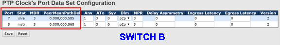
Switch B

Switch B
Port 7 = and get “ peer MeanPat hDel ” correction time Value
Port8 = Master and get “ peer MeanPathDel ” correction time Value
If PTP Port status
not is slave or master , mean is the PTP negotiation have problem .
Please check each switch and ptp clock config .